Thank you for visiting Nature.com. You are using a browser version with limited CSS support. For the best experience, we recommend that you use an updated browser (or disable Compatibility Mode in Internet Explorer). In addition, to ensure continued support, we show the site without styles and JavaScript.
Sliders showing three articles per slide. Use the back and next buttons to move through the slides, or the slide controller buttons at the end to move through each slide.
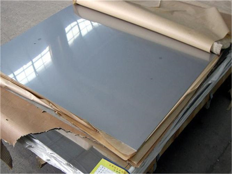
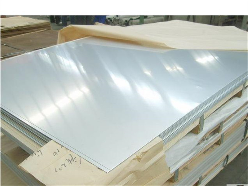
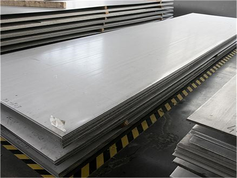
ASTM A240 304 316 Stainless Steel Medium Thick Plate Can Be Cut And Customized China Factory Price
Material Grade: 201/304/304l/316/316l/321/309s/310s/410/420/430/904l/2205/2507
Type:Ferritic, Austenite, Martensite, Duplex
Technology:Cold Rolled and Hot Rolled
Certifications: ISO9001, CE, SGS every year
Service: Third party testing
Delivery: within 10-15 days or considering the quantity
Stainless steel is an iron alloy that has a minimum Chromium content of 10.5 per cent. The Chromium content produces a thin chromium oxide film on the steel’s surface called a passivation layer. This layer prevents corrosion from occurring on the steel surface; the greater the amount of Chromium in the steel, the greater the corrosion resistance.
The steel also contains varied amounts of other elements such as Carbon, Silicon and Manganese. Other elements can be added to increase corrosion resistance (Nickel) and formability (Molybdenum).
| Material Supply: | ||||||||||||
|
ASTM/ASME |
EN Grade |
Chemical Component % |
||||||||||
|
C |
Cr |
Ni |
Mn |
P | S | Mo | Si | Cu | N | Other | ||
|
201 |
|
≤0.15 |
16.00-18.00 |
3.50-5.50 |
5.50-7.50 |
≤0.060 | ≤0.030 | - | ≤1.00 | - | ≤0.25 | - |
|
301 |
1.4310 |
≤0.15 |
16.00-18.00 |
6.00-8.00 |
≤2.00 |
≤0.045 | ≤0.030 | - | ≤1.00 | - |
0.1 |
- |
|
304 |
1.4301 |
≤0.08 |
18.00-20.00 |
8.00-10.00 |
≤2.00 |
≤0.045 | ≤0.030 | - | ≤0.75 | - | - | - |
|
304L |
1.4307 |
≤0.030 |
18.00-20.00 |
8.00-10.00 |
≤2.00 |
≤0.045 | ≤0.030 | - | ≤0.75 | - | - | - |
|
304H |
1.4948 |
0.04~0.10 |
18.00-20.00 |
8.00-10.00 |
≤2.00 |
≤0.045 | ≤0.030 | - | ≤0.75 | - | - | - |
|
309S |
1.4828 |
≤0.08 |
22.00-24.00 |
12.00-15.00 |
≤2.00 |
≤0.045 | ≤0.030 | - | ≤0.75 | - | - | - |
|
309H |
|
0.04~0.10 |
22.00-24.00 |
12.00-15.00 |
≤2.00 |
≤0.045 | ≤0.030 | - | ≤0.75 | - | - | - |
|
310S |
1.4842 |
≤0.08 |
24.00-26.00 |
19.00-22.00 |
≤2.00 |
≤0.045 | ≤0.030 | - | ≤1.5 | - | - | - |
|
310H |
1.4821 |
0.04~0.10 |
24.00-26.00 |
19.00-22.00 |
≤2.00 |
≤0.045 | ≤0.030 | - | ≤1.5 | - | - | - |
|
316 |
1.4401 |
≤0.08 |
16.00-18.50 |
10.00-14.00 |
≤2.00 |
≤0.045 | ≤0.030 | 2.00-3.00 | ≤0.75 | - | - | - |
|
316L |
1.4404 |
≤0.030 |
16.00-18.00 |
10.00-14.00 |
≤2.00 |
≤0.045 | ≤0.030 | 2.00-3.00 | ≤0.75 | - | - | - |
|
316H |
|
0.04~0.10 |
16.00-18.00 |
10.00-14.00 |
≤2.00 |
≤0.045 | ≤0.030 | 2.00-3.00 | ≤0.75 | - | 0.10-0.22 | - |
|
316Ti |
1.4571 |
≤0.08 |
16.00-18.50 |
10.00-14.00 |
≤2.00 |
≤0.045 | ≤0.030 | 2.00-3.00 | ≤0.75 | - | - | Ti5(C+N)~0.7 |
|
317L |
1.4438 |
≤0.03 |
18.00-20.00 |
11.00-15.00 |
≤2.00 |
≤0.045 | ≤0.030 | 3.00-4.00 | ≤0.75 | - |
0.1 |
- |
|
321 |
1.4541 |
≤0.08 |
17.00-19.00 |
9.00-12.00 |
≤2.00 |
≤0.045 | ≤0.030 | - | ≤0.75 | - |
0.1 |
Ti5(C+N)~0.7 |
|
321H |
1.494 |
0.04~0.10 |
17.00-19.00 |
9.00-12.00 |
≤2.00 |
≤0.045 | ≤0.030 | - | ≤0.75 | - |
0.1 |
Ti4(C+N)~0.7 |
|
347 |
1.4550 |
≤0.08 |
17.00-19.00 |
9.00-13.00 |
≤2.00 |
≤0.045 | ≤0.030 | - | ≤0.75 | - | - | Nb≥10*C%-1.0 |
|
347H |
1.4942 |
0.04~0.10 |
17.00-19.00 |
9.00-13.00 |
≤2.00 |
≤0.045 | ≤0.030 | - | ≤0.75 | - | - | Nb≥8*C%-1.0 |
|
409 |
S40900 |
≤0.03 |
10.50-11.70 |
0.5 |
≤1.00 |
≤0.040 | ≤0.020 | - | ≤1.00 | - | 0.03 | Ti6(C+N)-0.5 Nb0.17 |
|
410 |
1Cr13 |
0.08~0.15 |
11.50-13.50 |
- |
≤1.00 |
≤0.040 | ≤0.030 | - | ≤1.00 | - | - | - |
|
420 |
2Cr13 |
≥0.15 |
12.00-14.00 |
- |
≤1.00 |
≤0.040 | ≤0.030 | - | ≤1.00 | - | - | - |
|
430 |
S43000 |
≤0.12 |
16.00-18.00 |
0.75 |
≤1.00 |
≤0.040 | ≤0.030 | - | ≤1.00 | - | - | - |
|
431 |
1Cr17Ni2 |
≤0.2 |
15.00-17.00 |
1.25-2.50 |
≤1.00 |
≤0.040 | ≤0.030 | - | ≤1.00 | - | - | - |
|
440C |
11Cr17 |
0.95-1.20 |
16.00-18.00 |
- |
≤1.00 |
≤0.040 | ≤0.030 | 0.75 | ≤1.00 | - | - | - |
|
17-4PH |
630/1.4542 |
≤0.07 |
15.50-17.50 |
3.00-5.00 |
≤1.00 |
≤0.040 | ≤0.030 | - | ≤1.00 | 3.00-5.00 | - | Nb+Ta:0.15-0.45 |
|
17-7PH |
631 |
≤0.09 |
16.00-18.00 |
6.50-7.50 |
≤1.00 |
≤0.040 | ≤0.030 | - | ≤1.00 | - | - | Al 0.75-1.50 |
| size supply: | ||||||
| 3 | 3*1000*2000 | 3*1219*2438 | 3*1500*3000 | 3*1500*6000 | ||
| 4 | 4*1000*2000 | 4*1219*2438 | 4*1500*3000 | 4*1500*6000 | ||
| 5 | 5*1000*2000 | 5*1219*2438 | 5*1500*3000 | 5*1500*6000 | ||
| 6 | 6*1000*2000 | 6*1219*2438 | 6*1500*3000 | 6*1500*6000 | ||
| 7 | 7*1000*2000 | 7*1219*2438 | 7*1500*3000 | 7*1500*6000 | ||
| 8 | 8*1000*2000 | 8*1219*2438 | 8*1500*3000 | 8*1500*6000 | ||
| 9 | 9*1000*2000 | 9*1219*2438 | 9*1500*3000 | 9*1500*6000 | ||
| 10.0 | 10*1000*2000 | 10*1219*2438 | 10*1500*3000 | 10*1500*6000 | ||
| 12.0 | 12*1000*2000 | 12*1219*2438 | 12*1500*3000 | 12*1500*6000 | ||
| 14.0 | 14*1000*2000 | 14*1219*2438 | 14*1500*3000 | 14*1500*6000 | ||
| 16.0 | 16*1000*2000 | 16*1219*2438 | 14*1500*3000 | 14*1500*6000 | ||
| 18.0 | 18*1000*2000 | 18*1219*2438 | 18*1500*3000 | 18*1500*6000 | ||
| 20 | 20*1000*2000 | 20*1219*2438 | 20*1500*3000 | 20*1500*6000 |
Behavior of high carbon martensitic stainless steel (HCMSS) consisting of approximately 22.5 vol. % carbides with a high content of chromium (Cr) and vanadium (V), was fixed by electron beam melting (EBM). The microstructure is composed of martensite and residual austenite phases, submicron high V and micron high Cr carbides are evenly distributed, and the hardness is relatively high. CoF decreases by approximately 14.1% with increasing steady state load due to transfer of material from the worn track to the opposing body. Compared to martensitic tool steels treated in the same way, the wear rate of HCMSS is almost the same at low applied loads. The dominant wear mechanism is the removal of the steel matrix by abrasion followed by oxidation of the wear track, while three-component abrasive wear occurs with increasing load. Areas of plastic deformation under the wear scar identified by cross-sectional hardness mapping. Specific phenomena that occur as wear conditions increase are described as carbide cracking, high vanadium carbide tearout, and die cracking. This research sheds light on the wear characteristics of HCMSS additive manufacturing, which could pave the way for the production of EBM components for wear applications ranging from shafts to plastic injection molds.
Stainless steel (SS) is a versatile family of steels widely used in aerospace, automotive, food and many other applications due to their high corrosion resistance and suitable mechanical properties1,2,3. Their high corrosion resistance is due to the high content of chromium (more than 11.5 wt. %) in HC, which contributes to the formation of an oxide film with a high chromium content on the surface1. However, most stainless steel grades have a low carbon content and therefore have limited hardness and wear resistance, resulting in reduced service life in wear-related devices such as aerospace landing components4. Usually they have a low hardness (in the range of 180 to 450 HV), only some heat treated martensitic stainless steels have high hardness (up to 700 HV) and high carbon content (up to 1.2 wt%), which can contribute to the formation of martensite. 1. In short, a high carbon content lowers the martensitic transformation temperature, allowing the formation of a fully martensitic microstructure and the acquisition of a wear-resistant microstructure at high cooling rates. Hard phases (eg, carbides) can be added to the steel matrix to further improve the wear resistance of the die.
The introduction of additive manufacturing (AM) can produce new materials with desired composition, microstructural features, and superior mechanical properties5,6. For example, powder bed melting (PBF), one of the most commercialized additive welding processes, involves the deposition of pre-alloyed powders to form closely shaped parts by melting the powders using heat sources such as lasers or electron beams7. Several studies have shown that additively machined stainless steel parts can outperform traditionally made parts. For example, austenitic stainless steels subjected to additive processing have been shown to have superior mechanical properties due to their finer microstructure (i.e., Hall-Petch relationships)3,8,9. Heat treatment of AM-treated ferritic stainless steel produces additional precipitates that provide mechanical properties similar to their conventional counterparts3,10. Adopted dual-phase stainless steel with high strength and hardness, processed by additive processing, where improved mechanical properties are due to chromium-rich intermetallic phases in the microstructure11. In addition, improved mechanical properties of additive hardened martensitic and PH stainless steels can be obtained by controlling retained austenite in the microstructure and optimizing machining and heat treatment parameters 3,12,13,14.
To date, the tribological properties of AM austenitic stainless steels have received more attention than other stainless steels. The tribological behavior of laser melting in a layer of powder (L-PBF) treated with 316L was studied as a function of the AM processing parameters. It has been shown that minimizing porosity by reducing scanning speed or increasing laser power can improve wear resistance15,16. Li et al.17 tested dry sliding wear under various parameters (load, frequency and temperature) and showed that room temperature wear is the main wear mechanism, while increasing sliding speed and temperature promotes oxidation. The resulting oxide layer ensures the operation of the bearing, friction decreases with increasing temperature, and the wear rate increases at higher temperatures. In other studies, the addition of TiC18, TiB219, and SiC20 particles to an L-PBF treated 316L matrix improved wear resistance by forming a dense work hardened friction layer with an increase in the volume fraction of hard particles. A protective oxide layer has also been observed in L-PBF12 treated PH steel and SS11 duplex steel, indicating that limiting retained austenite by post-heat treatment12 can improve wear resistance. As summarized here, the literature is mainly focused on the tribological performance of the 316L SS series, while there is little data on the tribological performance of a series of martensitic additively manufactured stainless steels with a much higher carbon content.
Electron Beam Melting (EBM) is a technique similar to L-PBF capable of forming microstructures with refractory carbides such as high vanadium and chromium carbides due to its ability to reach higher temperatures and scan rates 21, 22. Existing literature on EBM processing of stainless steel is mainly focused on determining the optimal ELM processing parameters to obtain a microstructure without cracks and pores and improve mechanical properties23, 24, 25, 26, while work on the tribological properties of EBM treated stainless steel. So far, the wear mechanism of high-carbon martensitic stainless steel treated with ELR has been studied under limited conditions, and severe plastic deformation has been reported to occur under abrasive (sandpaper test), dry, and mud-erosion conditions27.
This study investigated the wear resistance and frictional properties of high carbon martensitic stainless steel treated with ELR under dry sliding conditions described below. First, microstructural features were characterized using scanning electron microscopy (SEM), energy dispersive X-ray spectroscopy (EDX), X-ray diffraction and image analysis. The data obtained with these methods is then used as the basis for observations of tribological behavior through dry reciprocating tests under various loads, and finally the worn surface morphology is examined using SEM-EDX and laser profilometers. The wear rate was quantified and compared with similarly treated martensitic tool steels. This was done in order to create a basis for comparing this SS system with more commonly used wear systems with the same type of treatment. Finally, a cross-sectional map of the wear path is shown using a hardness mapping algorithm that reveals the plastic deformation that occurs during contact. It should be noted that the tribological tests for this study were conducted to better understand the tribological properties of this new material, and not to simulate a specific application. This study contributes to a better understanding of the tribological properties of a new additively produced martensitic stainless steel for wear applications that require operation in harsh environments.
Samples of high carbon martensitic stainless steel (HCMSS) treated with ELR under the brand name Vibenite® 350 were developed and supplied by VBN Components AB, Sweden. The nominal chemical composition of the sample: 1.9 C, 20.0 Cr, 1.0 Mo, 4.0 V, 73.1 Fe (wt.%). First, dry sliding specimens (40 mm × 20 mm × 5 mm) were made from the obtained rectangular specimens (42 mm × 22 mm × 7 mm) without any post-thermal treatment using electrical discharge machining (EDM). Then the samples were successively ground with SiC sandpaper with a grain size of 240 to 2400 R to obtain a surface roughness (Ra) of about 0.15 μm. In addition, specimens of EBM-treated high-carbon martensitic tool steel (HCMTS) with a nominal chemical composition of 1.5 C, 4.0 Cr, 2.5 Mo, 2.5 W, 4.0 V, 85.5 Fe (wt. .%) (commercially known as Vibenite® 150) Also prepared in the same way. HCMTS contains 8% carbides by volume and is only used to compare HCMSS wear rate data.
Microstructural characterization of HCMSS was performed using an SEM (FEI Quanta 250, USA) equipped with an energy dispersive X-ray (EDX) XMax80 detector from Oxford Instruments. Three random photomicrographs containing 3500 µm2 were taken in backscattered electron (BSE) mode and then analyzed using image analysis (ImageJ®)28 to determine area fraction (i.e. volume fraction), size and shape. Due to the observed characteristic morphology, the area fraction was taken equal to the volume fraction. In addition, the shape factor of carbides is calculated using the shape factor equation (Shfa):
Here Ai is the area of the carbide (µm2) and Pi is the perimeter of the carbide (µm)29. To identify the phases, powder X-ray diffraction (XRD) was performed using an X-ray diffractometer (Bruker D8 Discover with a LynxEye 1D strip detector) with Co-Kα radiation (λ = 1.79026 Å). Scan the sample over the 2θ range from 35° to 130° with a step size of 0.02° and a step time of 2 seconds. The XRD data was analyzed using the Diffract.EVA software, which updated the crystallographic database in 2021. In addition, a Vickers hardness tester (Struers Durascan 80, Austria) was used to determine the microhardness. According to the ASTM E384-17 30 standard, 30 prints were made on metallographically prepared samples in 0.35 mm increments for 10 s at 5 kgf. The authors have previously characterized the microstructural features of HCMTS31.
A ball plate tribometer (Bruker Universal Mechanical Tester Tribolab, USA) was used to perform dry reciprocating wear tests, the configuration of which is detailed elsewhere31. The test parameters are as follows: according to standard 32 ASTM G133-05, load 3 N, frequency 1 Hz, stroke 3 mm, duration 1 hour. Aluminum oxide balls (Al2O3, accuracy class 28/ISO 3290) with a diameter of 10 mm with a macrohardness of about 1500 HV and a surface roughness (Ra) of about 0.05 µm, provided by Redhill Precision, Czech Republic, were used as counterweights. Balancing was chosen to prevent the effects of oxidation that can occur due to balancing and to better understand the wear mechanisms of specimens under severe wear conditions. It should be noted that the test parameters are the same as in Ref.8 in order to compare wear rate data with existing studies. In addition, a series of reciprocating tests with a load of 10 N was carried out to verify the tribological performance at higher loads, while other test parameters remained constant. Initial contact pressures according to Hertz are 7.7 MPa and 11.5 MPa at 3 N and 10 N, respectively. During the wear test, the friction force was recorded at a frequency of 45 Hz and the average coefficient of friction (CoF) was calculated. For each load, three measurements were taken under ambient conditions.
The wear trajectory was examined using the SEM described above, and the EMF analysis was performed using Aztec Acquisition wear surface analysis software. The worn surface of the paired cube was examined using an optical microscope (Keyence VHX-5000, Japan). A non-contact laser profiler (NanoFocus µScan, Germany) scanned the wear mark with a vertical resolution of ±0.1 µm along the z axis and 5 µm along the x and y axes. The wear scar surface profile map was created in Matlab® using x, y, z coordinates obtained from the profile measurements. Several vertical wear path profiles extracted from the surface profile map are used to calculate the wear volume loss on the wear path. The volume loss was calculated as the product of the mean cross-sectional area of the wire profile and the length of the wear track, and additional details of this method have been previously described by the authors33. From here, the specific wear rate (k) is obtained from the following formula:
Here V is the volume loss due to wear (mm3), W is the applied load (N), L is the sliding distance (mm), and k is the specific wear rate (mm3/Nm)34. Friction data and surface profile maps for HCMTS are included in supplementary material (Supplementary Figure S1 and Figure S2) to compare HCMSS wear rates.
In this study, a cross-sectional hardness map of the wear path was used to demonstrate the plastic deformation behavior (i.e. work hardening due to contact pressure) of the wear zone. The polished samples were cut with an aluminum oxide cutting wheel on a cutting machine (Struers Accutom-5, Austria) and polished with SiC sandpaper grades from 240 to 4000 P along the thickness of the samples. Microhardness measurement at 0.5 kgf 10 s and 0.1 mm distance in accordance with ASTM E348-17. The prints were placed on a 1.26 × 0.3 mm2 rectangular grid approximately 60 µm below the surface (Figure 1) and then a hardness map was rendered using custom Matlab® code described elsewhere35. In addition, the microstructure of the cross section of the wear zone was examined using SEM.
Schematic of the wear mark showing the location of the cross section (a) and an optical micrograph of the hardness map showing the mark identified in the cross section (b).
The microstructure of HCMSS treated with ELP consists of a homogeneous carbide network surrounded by a matrix (Fig. 2a, b). EDX analysis showed that the gray and dark carbides were chromium and vanadium rich carbides, respectively (Table 1). Calculated from image analysis, the volume fraction of carbides is estimated to be ~22.5% (~18.2% high chromium carbides and ~4.3% high vanadium carbides). The average grain sizes with standard deviations are 0.64 ± 0.2 µm and 1.84 ± 0.4 µm for V and Cr rich carbides, respectively (Fig. 2c, d). High V carbides tend to be rounder with a shape factor (±SD) of about 0.88±0.03 because shape factor values close to 1 correspond to round carbides. In contrast, high chromium carbides are not perfectly round, with a shape factor of about 0.56 ± 0.01, which may be due to agglomeration. Martensite (α, bcc) and retained austenite (γ’, fcc) diffraction peaks were detected on the HCMSS X-ray pattern as shown in Fig. 2e. In addition, the X-ray pattern shows the presence of secondary carbides. High chromium carbides have been identified as M3C2 and M23C6 type carbides. According to the literature data,36,37,38 diffraction peaks of VC carbides were recorded at ≈43° and 63°, suggesting that the VC peaks were masked by the M23C6 peaks of chromium-rich carbides (Fig. 2e).
Microstructure of high-carbon martensitic stainless steel treated with EBL (a) at low magnification and (b) at high magnification, showing chromium and vanadium rich carbides and a stainless steel matrix (electron backscattering mode). Bar graphs showing the grain size distribution of chromium-rich (c) and vanadium-rich (d) carbides. The X-ray pattern shows the presence of martensite, retained austenite and carbides in the microstructure (d).
The average microhardness is 625.7 + 7.5 HV5, showing a relatively high hardness compared to conventionally processed martensitic stainless steel (450 HV)1 without heat treatment. The nanoindentation hardness of high V carbides and high Cr carbides is reported to be between 12 and 32.5 GPa39 and 13–22 GPa40, respectively. Thus, the high hardness of HCMSS treated with ELP is due to the high carbon content, which promotes the formation of a carbide network. Thus, HSMSS treated with ELP shows good microstructural characteristics and hardness without any additional post-thermal treatment.
Curves of the average coefficient of friction (CoF) for samples at 3 N and 10 N are presented in Figure 3, the range of minimum and maximum friction values is marked with translucent shading. Each curve shows a run-in phase and a steady state phase. The run-in phase ends at 1.2 m with a CoF (±SD) of 0.41 ± 0.24.3 N and at 3.7 m with a CoF of 0.71 ± 0.16.10 N, before entering the phase steady state when friction stops. does not change quickly. Due to the small contact area and the rough initial plastic deformation, the friction force increased rapidly during the running-in stage at 3 N and 10 N, where a higher friction force and a longer sliding distance occurred at 10 N, which may be due to the fact that Compared with 3 N, surface damage is higher. For 3 N and 10 N, the CoF values in the stationary phase are 0.78 ± 0.05 and 0.67 ± 0.01, respectively. CoF is practically stable at 10 N and increases gradually at 3 N. In the limited literature, the CoF of L-PBF treated stainless steel compared to ceramic reaction bodies at low applied loads ranges from 0.5 to 0.728, 20, 42, which is in good agreement with measured CoF values in this study. The decrease in CoF with increasing load in steady state (about 14.1%) can be attributed to surface degradation occurring at the interface between the worn surface and the counterpart, which will be further discussed in the next section through the analysis of the surface of the worn samples.
Friction coefficients of VSMSS specimens treated with ELP on sliding paths at 3 N and 10 N, a stationary phase is marked for each curve.
The specific wear rates of HKMS (625.7 HV) are estimated at 6.56 ± 0.33 × 10⁻⁶ mm3/Nm and 9.66 ± 0.37 × 10⁻⁶ mm3/Nm at 3 N and 10 N, respectively (Fig. . 4). Thus, the wear rate increases with increasing load, which is in good agreement with existing studies on austenite treated with L-PBF and PH SS17,43. Under the same tribological conditions, the wear rate at 3 N is about one-fifth that for austenitic stainless steel treated with L-PBF (k = 3.50 ± 0.3 × 10⁻⁵ mm3/Nm, 229 HV), as in the previous case. 8. In addition, the wear rate of HCMSS at 3 N was significantly lower than conventionally machined austenitic stainless steels and, in particular, higher than highly isotropic pressed ones (k = 4.20 ± 0.3 × 10⁻⁵ mm3). /Nm, 176 HV) and cast (k = 4.70 ± 0.3 × 10⁻⁵ mm3/Nm, 156 HV) machined austenitic stainless steel, 8, respectively. Compared to these studies in the literature, the improved wear resistance of HCMSS is attributed to the high carbon content and the formed carbide network resulting in higher hardness than additively machined austenitic stainless steels conventionally machined. To further study the wear rate of HCMSS specimens, a similarly machined high carbon martensitic tool steel (HCMTS) specimen (with a hardness of 790 HV) was tested under similar conditions (3 N and 10 N) for comparison; Supplementary material is the HCMTS Surface Profile Map (Supplementary Figure S2). The wear rate of HCMSS (k = 6.56 ± 0.34 × 10⁻⁶ mm3/Nm) is almost the same as that of HCMTS at 3 N (k = 6.65 ± 0.68 × 10⁻⁶ mm3/Nm), which indicates excellent wear resistance. These characteristics are mainly attributed to the microstructural features of HCMSS (i.e. high carbide content, size, shape and distribution of carbide particles in the matrix, as described in Section 3.1). As previously reported31,44, the carbide content affects the width and depth of the wear scar and the mechanism of micro-abrasive wear. However, the carbide content is insufficient to protect the die at 10 N, resulting in increased wear. In the following section, wear surface morphology and topography is used to explain the underlying wear and deformation mechanisms that affect the wear rate of HCMSS. At 10 N, the wear rate of VCMSS (k = 9.66 ± 0.37 × 10⁻⁶ mm3/Nm) is higher than that of VKMTS (k = 5.45 ± 0.69 × 10⁻⁶ mm3/Nm). On the contrary, these wear rates are still quite high: under similar test conditions, the wear rate of coatings based on chromium and stellite is lower than that of HCMSS45,46. Finally, due to the high hardness of the alumina (1500 HV), the mating wear rate was negligible and signs of material transfer from the specimen to the aluminum balls were found.
Specific wear in ELR machining of high carbon martensitic stainless steel (HMCSS), ELR machining of high carbon martensitic tool steel (HCMTS) and L-PBF, casting and high isotropic pressing (HIP) machining of austenitic stainless steel (316LSS) at various application speeds are loaded. The scatterplot shows the standard deviation of the measurements. Data for austenitic stainless steels are taken from 8.
While hardfacings such as chromium and stellite can provide better wear resistance than additively machined alloy systems, additive machining can (1) improve microstructure, especially for materials with a wide variety of densities. operations on the end part; and (3) creation of new surface topologies such as integrated fluid dynamic bearings. In addition, AM offers geometric design flexibility. This study is particularly novel and important as it is critical to elucidate the wear characteristics of these newly developed metal alloys with EBM, for which the current literature is very limited.
The morphology of the worn surface and the morphology of the worn samples at 3 N are shown in fig. 5, where the main wear mechanism is abrasion followed by oxidation. First, the steel substrate is plastically deformed and then removed to form grooves 1 to 3 µm deep, as shown in the surface profile (Fig. 5a). Due to the frictional heat generated by continuous sliding, the removed material remains at the interface of the tribological system, forming a tribological layer consisting of small islands of high iron oxide surrounding high chromium and vanadium carbides (Figure 5b and Table 2). ), as was also reported for austenitic stainless steel treated with L-PBF15,17. On fig. 5c shows intense oxidation occurring in the center of the wear scar. Thus, the formation of the friction layer is facilitated by the destruction of the friction layer (i.e., the oxide layer) (Fig. 5f) or the removal of material occurs in weak areas within the microstructure, thereby accelerating the removal of material. In both cases, the destruction of the friction layer leads to the formation of wear products at the interface, which may be the reason for the tendency for an increase in CoF in the steady state 3N (Fig. 3). In addition, there are signs of three-part wear caused by oxides and loose wear particles on the wear track, which ultimately leads to the formation of micro-scratches on the substrate (Fig. 5b, e)9,12,47.
Surface profile (a) and photomicrographs (b–f) of the wear surface morphology of high-carbon martensitic stainless steel treated with ELP at 3 N, cross-section of the wear mark in BSE mode (d) and optical microscopy of the wear surface at 3 N (g) alumina spheres.
Slip bands formed on the steel substrate, indicating plastic deformation due to wear (Fig. 5e). Similar results were also obtained in a study of the wear behavior of SS47 austenitic steel treated with L-PBF. The reorientation of vanadium-rich carbides also indicates plastic deformation of the steel matrix during sliding (Fig. 5e). Micrographs of the cross section of the wear mark show the presence of small round pits surrounded by microcracks (Fig. 5d), which may be due to excessive plastic deformation near the surface. The material transfer to the aluminum oxide spheres was limited, while the spheres remained intact (Fig. 5g).
The width and depth of wear of the samples increased with increasing load (at 10 N), as shown in the surface topography map (Fig. 6a). Abrasion and oxidation are still the dominant wear mechanisms, and an increase in the number of micro-scratches on the wear track indicates that three-part wear also occurs at 10 N (Fig. 6b). EDX analysis showed the formation of iron-rich oxide islands. The Al peaks in the spectra confirmed that the transfer of the substance from the counterparty to the sample occurred at 10 N (Fig. 6c and Table 3), while it was not observed at 3 N (Table 2). Three-body wear is caused by wear particles from oxide islands and analogs, where detailed EDX analysis revealed material carryover from analogs (Supplementary Figure S3 and Table S1). The development of oxide islands is associated with deep pits, which is also observed in 3N (Fig. 5). Cracking and fragmentation of carbides mainly occur in carbides rich in 10 N Cr (Fig. 6e, f). In addition, high V carbides flake and wear the surrounding matrix, which in turn causes three-part wear. A pit similar in size and shape to that of the high V carbide (highlighted in red circle) also appeared in the cross section of the track (Fig. 6d) (see carbide size and shape analysis. 3.1), indicating that the high V carbide V can flake off the matrix at 10 N. The round shape of high V carbides contributes to the pulling effect, while agglomerated high Cr carbides are prone to cracking (Fig. 6e, f). This failure behavior indicates that the matrix has exceeded its ability to withstand plastic deformation and that the microstructure does not provide sufficient impact strength at 10 N. Vertical cracking under the surface (Fig. 6d) indicates the intensity of plastic deformation that occurs during sliding. As the load increases there is a transfer of material from the worn track to the alumina ball (Fig. 6g), which can be steady state at 10 N. The main reason for the decrease in CoF values (Fig. 3).
Surface profile (a) and photomicrographs (b–f) of worn surface topography (b–f) of high-carbon martensitic stainless steel treated with EBA at 10 N, wear track cross-section in BSE mode (d) and optical microscope surface of alumina sphere at 10 N (g).
During sliding wear, the surface is subjected to antibody-induced compressive and shear stresses, resulting in significant plastic deformation under the worn surface34,48,49. Therefore, work hardening can occur below the surface due to plastic deformation, affecting the wear and deformation mechanisms that determine the wear behavior of a material. Therefore, cross-sectional hardness mapping (as detailed in Section 2.4) was performed in this study to determine the development of a plastic deformation zone (PDZ) below the wear path as a function of load. Since, as mentioned in the previous sections, clear signs of plastic deformation were observed below the wear trace (Fig. 5d, 6d), especially at 10 N.
On fig. Figure 7 shows cross-sectional hardness diagrams of wear marks of HCMSS treated with ELP at 3 N and 10 N. It is worth noting that these hardness values were used as an index to evaluate the effect of work hardening. The change in hardness below the wear mark is from 667 to 672 HV at 3 N (Fig. 7a), indicating that the work hardening is negligible. Presumably, due to the low resolution of the microhardness map (i.e. the distance between the marks), the applied hardness measurement method could not detect changes in hardness. On the contrary, PDZ zones with hardness values from 677 to 686 HV with a maximum depth of 118 µm and a length of 488 µm were observed at 10 N (Fig. 7b), which correlates with the width of the wear track (Fig. 6a)). Similar data on PDZ size variation with load was found in a wear study on SS47 treated with L-PBF. The results show that the presence of retained austenite affects the ductility of additively fabricated steels 3, 12, 50, and retained austenite transforms into martensite during plastic deformation (plastic effect of phase transformation), which enhances the work hardening of the steel. steel 51. Since the VCMSS sample contained retained austenite in accordance with the X-ray diffraction pattern discussed earlier (Fig. 2e), it was suggested that retained austenite in the microstructure could transform into martensite during contact, thereby increasing the hardness of PDZ (Fig. 7b). In addition, the formation of slip occurring on the wear track (Fig. 5e, 6f) also indicates plastic deformation caused by dislocation slip under the action of shear stress at sliding contact. However, the shear stress induced at 3 N was insufficient to produce a high dislocation density or the transformation of retained austenite to martensite observed by the method used, so work hardening was observed only at 10 N (Fig. 7b).
Cross-sectional hardness diagrams of wear tracks of high-carbon martensitic stainless steel subjected to electrical discharge machining at 3 N (a) and 10 N (b).
This study shows the wear behavior and microstructural characteristics of a new high carbon martensitic stainless steel treated with ELR. Dry wear tests were carried out in sliding under various loads, and worn samples were examined using electron microscopy, laser profilometer and hardness maps of cross-sections of wear tracks.
Microstructural analysis revealed a uniform distribution of carbides with a high content of chromium (~18.2% carbides) and vanadium (~4.3% carbides) in a matrix of martensite and retained austenite with relatively high microhardness. The dominant wear mechanisms are wear and oxidation at low loads, while three-body wear caused by stretched high-V carbides and loose grain oxides also contributes to wear at increasing loads. The wear rate is better than L-PBF and conventional machined austenitic stainless steels, and even similar to that of EBM machined tool steels at low loads. The CoF value decreases with increasing load due to the transfer of material to the opposite body. Using the cross-sectional hardness mapping method, the plastic deformation zone is shown below the wear mark. Possible grain refinement and phase transitions in the matrix can be further investigated using electron backscatter diffraction to better understand the effects of work hardening. The low resolution of the microhardness map does not allow visualization of wear zone hardness at low applied loads, so nanoindentation can provide higher resolution hardness changes using the same method.
This study presents for the first time a comprehensive analysis of the wear resistance and frictional properties of a new high carbon martensitic stainless steel treated with ELR. Considering the geometric design freedom of AM and the possibility of reducing machining steps with AM, this research could pave the way for the production of this new material and its use in wear-related devices from shafts to plastic injection molds with complicated cooling channel.
Bhat, B.N. Aerospace Materials and Applications, vol. 255 (American Society of Aeronautics and Astronautics, 2018).
Bajaj, P. et al. Steel in additive manufacturing: a review of its microstructure and properties. alma mater. the science. project. 772, (2020).
Felli, F., Brotzu, A., Vendittozzi, C., Paolozzi, A. and Passeggio, F. Damage to the wear surface of EN 3358 stainless steel aerospace components during sliding. Brotherhood. Ed. Integra Strut. 23, 127–135 (2012).
Debroy, T. et al. Additive Manufacturing of Metal Components – Process, Structure, and Performance. programming. alma mater. the science. 92, 112–224 (2018).
Herzog D., Sejda V., Vicisk E. and Emmelmann S. Production of metal additives. (2016). https://doi.org/10.1016/j.actamat.2016.07.019.
ASTM International. Standard terminology for additive manufacturing technology. Fast production. Assistant professor. https://doi.org/10.1520/F2792-12A.2 (2013).
Bartolomeu F. et al. Mechanical and tribological properties of 316L stainless steel – comparison of selective laser melting, hot pressing and conventional casting. Add to. manufacturer. 16, 81–89 (2017).
Bakhshwan, M., Myant, K.W., Reddichoff, T., and Pham, M.S. Microstructure Contribution to Additively Fabricated 316L Stainless Steel Dry Sliding Wear Mechanisms and Anisotropy. alma mater. dec. 196, 109076 (2020).
Bogelein T., Drypondt S.N., Pandey A., Dawson K. and Tatlock G.J. Mechanical response and mechanisms of deformation of steel structures hardened with iron oxide dispersion obtained by selective laser melting. magazine. 87, 201–215 (2015).
Saeidi K., Alvi S., Lofay F., Petkov V.I. and Akhtar, F. Higher order mechanical strength after heat treatment of SLM 2507 at room and elevated temperatures, aided by hard/ductile sigma precipitation. Metal (Basel). 9, (2019).
Lashgari, H.R., Kong, K., Adabifiroozjaei, E., and Li, S. Microstructure, post-heat reaction, and tribological properties of 3D-printed 17-4 PH stainless steel. Wearing 456–457, (2020).
Liu, Y., Tang, M., Hu, Q., Zhang, Y., and Zhang, L. Densification behavior, microstructure evolution, and mechanical properties of TiC/AISI420 stainless steel composites fabricated by selective laser melting. alma mater. dec. 187, 1–13 (2020).
Zhao X. et al. Fabrication and characterization of AISI 420 stainless steel using selective laser melting. alma mater. manufacturer. process. 30, 1283–1289 (2015).
Sun Y., Moroz A. and Alrbey K. Sliding wear characteristics and corrosion behavior of selective laser melting of 316L stainless steel. J. Alma mater. project. execute. 23, 518–526 (2013).
Shibata, K. et al. Friction and wear of powder-bed stainless steel under oil lubrication [J]. Tribiol. internal 104, 183–190 (2016).
Post time: Jun-09-2023