Thank you for visiting Nature.com. The version of browser you are using has limited CSS support. For best results, we recommend that you use a newer version of your browser (or disable Compatibility Mode in Internet Explorer). In the meantime, to ensure continued support, we are showing the site without styling or JavaScript.
Product Description
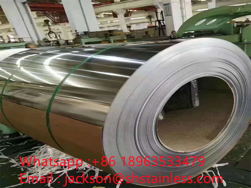
Stainless steel is a kind of corrosion resistant high alloy steel. It has an aesthetically pleasing surface that does
not require surface treatments such as colored plating or paint, and is not corroded, rusted or contaminated like ordinary steel.
The corrosion resistance of stainless steel coil mainly depends on its alloy composition (chromium, nickel, titanium, silicon,
aluminum, etc.) and the internal structure of stainless steel coil, among which the main role is chromium element. Chromium has
high chemical stability, can form passivation film on the steel surface, isolate the metal from the outside, protect the steel
plate from oxidation, increase the corrosion resistance of the steel plate. In order to ensure that the yield strength, tensile
strength, elongation and hardness of all kinds of stainless steel coil meet the requirements of mechanical properties, stainless
steel coil delivery must be annealing, solution treatment, aging treatment and other heat treatment.
Stainless steel coil Advantages:
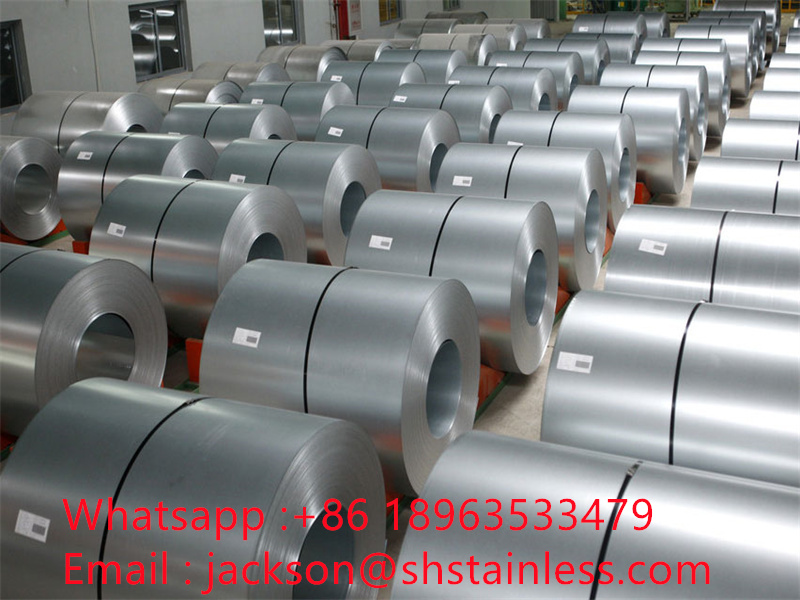
2.. Product specifications complete, material diversification;
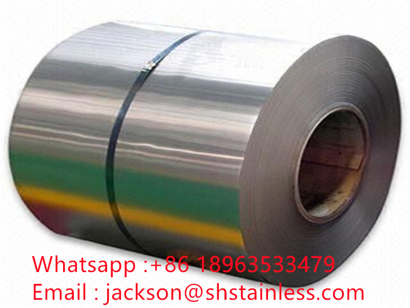
3. The surface quality of the steel coil is good, and the gloss and brightness are good
4. Stable chemical composition, pure steel, low inclusion content;
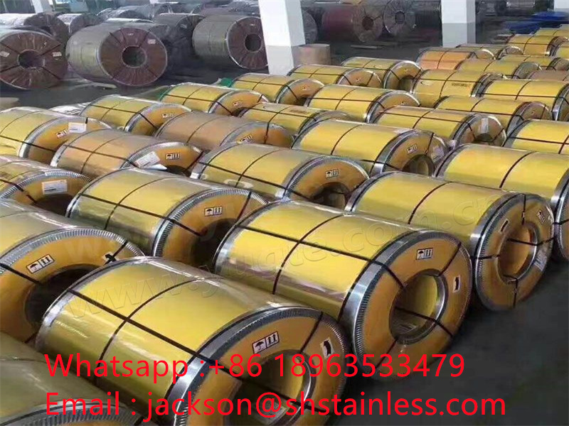
5. The outer packing is in good condition and the price is affordable;
Stainless steel coil Types: Mainly divided into 301 stainless steel roll, 304 stainless steel roll, 303 stainless steel roll, 302 stainless steel roll,
430 stainless steel roll, 201 stainless steel roll, 202 stainless steel roll, 304L stainless steel roll, 316 stainless steel roll,
316L stainless steel roll and so on.
Specification:
thickness specification is generally 0.025mm ~ 4mm. At the same time, manufacturers can also order various special specifications
of steel according to the needs of different users.
| Product Name | Stainless Steel Coil |
| Grade | 201/304/316/321,etc |
| Standard | JIS, AiSi, ASTM, GB, DIN, EN |
| Length | Customized |
| Width | Customized |
| Thickness | Customized |
| Tolerance | ±1% |
| Processing Service | Bending, Welding, Decoiling, Punching, Cutting |
| Surface finish | 2B/BA/HAIRLINE/8K/NO.4/No.1 |
| Package | Standard Seaworthy Package–wooden Pallet |
| Trade Term | FOB CIF CFR EXW Ect |
Product Photos :
Cold rolling negatively affects the formability of sheet metal. However, this is unavoidable when producing high quality panel surfaces. The effect of cold rolling on the forming limit of drawn sheets has not been comprehensively studied in the literature. This study uses experimental studies to observe the effect of different degrees of cold rolling thickness reduction on sheet metal formability. Since the experimental process of such tests is expensive, artificial intelligence is also used to predict the effect of cold thickness reduction on the formability of metal sheets. In this regard, St14 sheets were investigated using tensile, metallography, cold rolling, and Nakazima hemispherical die experiments. The obtained data was subsequently used to train and test the adaptive neural network fuzzy inference system (ANFIS) model. The results show that cold rolling reduces the formability of metal sheets under tensile loading conditions. In addition, due to a decrease in the thickness of the same metal sheet in a cold state, its tensile properties change significantly. The trained AFIS model was also successfully trained and tested in predicting the formation limit pattern. This model can be used to determine the ultimate forming strain under other thickness reduction conditions. It is discussed that the determination of the forming limit chart is not an inherent property of the chemical composition of the sheet metal and many other factors must be considered.
Determining the forming limits of sheet metal is critical to designing the geometry of the final sheet metal product. It is also one of the main quality control tests in deep drawing and sheet forming plants. Compared to tensile testing, determining molding limits requires a larger number of specimens and complex testing procedures. To avoid such costly and time-consuming tests, many analytical methods for calculating FLD using uniaxial tensile test curve data have been proposed in the literature1,2,3,4,5. However, uniaxial tensile curves are not a reliable source for determining forming limits6. Wu et al.7 showed through experiments that plates with small differences in uniaxial tensile curves have large differences in FLD due to the influence of their textures. Thus, although the tensile curve can provide an intuitive understanding of the molding limit, it is not sufficient to calculate an accurate FLD.
It is now recognized that the best way to obtain the ultimate forming curve is to carry out experimental tests on each batch of rolled sheets. The forming limit depends on many factors, including loading conditions, sheet thickness, and microstructural properties of the sheet. There is no model that takes into account all geometric, loading and microstructural parameters. Therefore, even if a model produces acceptable results in a particular situation, it is not reliable.
In recent years, the application of artificial intelligence and fuzzy logic has been growing in many areas of research. Elangovan et al 8 investigated the influence of geometric parameters on the forming limit using artificial neural networks (ANNs). ANN models are trained using datasets obtained from experiments. The trained model was further used to predict the FLD for a new set of leaf geometric parameters. Kotkunde et al.9 studied the behavior of the forming limit under different loads and temperature conditions using ANN. The molding limits predicted by the ANN method showed acceptable agreement with the experimental results. Extreme temperature and loading conditions are experimental and difficult to apply and test molding limits. A study by Mohamed et al.10 showed that ANN can be used to predict FLD. Derogar and Javanroudi11 demonstrated the capabilities of ANN in predicting sheet metal forming limits.
Another trend in artificial intelligence applications is the use of adaptive neural network fuzzy inference systems (ANFIS) to explore fuzzy problems12. This approach has recently become popular in physical modeling. To consider the application of the forming process, Lu et al used ANFIS to study the influence of geometric parameters on the final part shape during the hole expansion process. 13. The original dataset used to train ANFIS was collected using finite element modeling of the hole enlargement process. The results obtained by the trained ANFIS are compared with the experimental results. Esfahani et al used a genetic algorithm and the AFIS14 model to predict deformation during laser beam shaping. ANFIS demonstrates remarkable efficiency in obtaining accurate results at low computational cost. There are several examples in the literature of using AFIS to evaluate material properties13,15.
Theoretical and experimental studies have examined the influence of various parameters on FLD. However, most studies only consider one or two influencing parameters. The influence of workpiece and die geometry 16, 17, 18, strain loading path 19, loading rate 20 and lubrication 21 are considered as mechanical parameters affecting FLD. On the other hand, the second phase particle shape and distribution 22, production history and process 23, 24, grain size 4, material defects 25, texture 26, 27, 28 and chemical composition 29 are some limitations in the formation of metallurgical parameters. . In simulation and theoretical modeling, ignoring the influence of a certain parameter can lead to significant errors in FLD calculations.
In recent years, the influence of sheet microstructure on forming limit and processing performance has been reported. Amelrad and Assempour4 investigated the effect of grain size on the formability of 316L sheets using semi-realistic grain shapes. The simulation was carried out using crystal plasticity theory30. Xu et al.31 experimentally investigated the effect of thickness-grain size ratio on the forming limit and proposed left-handed FLD. The results show that high thickness-to-grain size ratio has a negative effect on formability. In another study by Yamaguchi and Mellor, increasing the thickness and grain size reduced the formability of the sheet32. The grain refinement in AZ31 improves ductility. However, the formability of AZ31 sheets is independent of grain size as experimentally demonstrated by Azghandi et al.33.
The effects of texture are thoroughly investigated through experiments and crystal plasticity simulations. Wu et al.7 used experimental and crystal plasticity methods to determine the forming limit of aluminum sheets. They concluded that even if the differences in sheet tensile behavior are small, differences in texture can lead to significant differences in the resulting limit curves. Therefore, tensile curves are not a reliable source for predicting molding limits without considering other factors such as texture. Barlat28 used the homogenization method of polycrystalline aggregates to obtain the yield surface of metal sheets. In addition, the obtained yield surface is used to predict the forming limit. Barnwal et al.34 demonstrated that the forming limit of aluminum sheets is highly dependent on the texture of the sheets.
To the best of the authors’ knowledge, the effect of cold working on sheet metal formability has not been discussed in the literature. Therefore, in this study, the application of ANFIS to determine the forming limit diagram using cold rolling experimental data is applied to St14 steel plates. Experimental tensile and FLD tests were used to train and test the ANFIS model. The trained ANFIS model is then used to predict FLD under other cold rolling conditions. The novelty of this work is the creation of a simple neuro-fuzzy network that can be used to replace complex and expensive experiments with acceptable error bounds. To the best of the authors’ knowledge, this is the first time that fuzzy logic has been used to interpret and classify input data for FLD prediction.
St14 low carbon steel sheets are widely used in automobile body forming due to its high formability. In this study, plates of thickness \(1.5 \pm 0.03{\text{mm}}\) were used to test the formability under different rolling conditions. The chemical composition of the plates is given in Table 1. The panels as received are heat treated to mitigate the effects of historical processes on the panels. Heat treatment was carried out at a temperature of 900°C and the sheet was kept at this temperature for 1 hour. Cool the sheets to room temperature in the oven. This process creates a more uniform microstructure.
After heat treatment, the plates were cut into strips 12 cm wide and etched with a perchloric acid solution to remove surface scale. The sheets are additionally cold rolled until the thickness is reduced by 25% and 45%.
The microstructure of St14 steel was revealed by metallographic methods. The resulting heat-treated and rolled samples were cut along the rolling direction and sections of the plates were mounted. The samples were then ground with 3000 grit sandpaper and polished with 1 µm diamond abrasive paste. Use 2% nitric acid to identify particles in the sample. The results for the resulting sample are shown in Figure 1, and the results for the processed sample are shown in Figure 2. As shown in Figure 1, the grain shape is actually spherical, but a slight stretch can be seen in the overall structure, indicating temper training after the spheroidization process. Consequently, the microstructure of the resulting metal plate contains spheroidized cementite. Other forms of cementite can affect the structure of sheet metal after heat treatment. After heat treatment, the grain size increases, as shown in Figure 2a. After heat treatment, the grains had a spherical shape and no traces of spheroidized cementite were found, which indicates strong decarburization in the oxygen atmosphere in the furnace. In Fig. Figure 2 also shows the cold-rolled microstructure with a thickness reduction of 25% (Fig. 2b) and 45% (Fig. 2c). The purpose of presenting microstructure details is their significant impact on the forming limits, for example, the same thickness and chemical composition with different grain morphologies lead to completely different formability. For future comparisons, we believe it is necessary to report the mechanical and metallurgical properties of the plates, as well as the test conditions, whenever possible.
Microstructure (top) and 25% (center) and 45% (bottom) thickness reduction after heat treatment with St14 (100×, 2% nitrate for 20 seconds).
Tensile tests were performed using small specimens according to ASTM E8 standard procedures. The technical tensile curve of the heat-treated sample is shown in Figure 3. As shown in the figure, cold rolling significantly reduces the ductility of the sheet, increases the yield and tensile strength. Due to aging after heat treatment, the samples showed little yield stress phenomenon before rolling. The ductility of the rolled sample decreased from 36% strain to 9.5%. In addition, after cold rolling thinning by 25 and 45%, the tensile strength increased from 256 to 379 MPa and 438 MPa, respectively.
The Nakazima test is used to determine the limiting formation diagram. The diameter of the spherical punch is 50 mm, and all surfaces of the punch and sheet specimen are fully lubricated to minimize friction. Cut the specimens into bone and rectangular shapes as shown in Figure 4. The surface of the specimen is sanded in preparation for the etching marking process. Before testing, circular and square grid marks were engraved on the specimens to measure the major and minor major strains after molding using the apparatus shown in Figure 5. The strain was measured after molding using Myler tapes.
The formation of Nakasim limits the sample size and cutting of sheets. The scale on the plates is caused by the oxygen-containing atmosphere in the furnace, which was grounded before Nakazima’s test.
In Fig. Figure 6 shows an example of a deformed sample. The strain at the safe point and at the constriction point was measured in the area surrounding the constriction and in the region of the constriction. Subsequently, forming limit diagrams were constructed using the safe points of all deformed samples, which represented different loading paths from uniaxial tension to equal biaxial tension. The FLD results are shown in Figure 7. Similar to the decrease in ductility, the formability of the cold-rolled plate specimens decreased significantly, and as the thickness reduction increased, the formability limit reached the lowest point in the figure. This is in contrast to ductility, where increasing thickness reduction has a negligible effect on the fracture strain in the experiments conducted in this study.
As shown in Figure 8, the thickness reduction effect of St14 sheets was simulated using the developed ANFIS network. The advantage of using ANFIS is the use of membership functions to classify input values. For example, crimping can be divided into “extreme” crimping, “moderate” crimping and “pass rolling”. On this basis, different responses may be assigned to each category. In an ANN, a range of all input values similar to the thickness reduction value must be fitted using the same function. The input layer consists of three independent parameters: compression, the value of test strain under uniaxial tension at the point of contraction, and microdeformation. Therefore, the network has only one output major strain, which will be coupled to the corresponding minor strain to indicate a single strain on the resulting limit curve. Among the hidden layers, the first layer is called the fuzzification layer, where the input values are converted into the values of their membership functions. In total there are no more than \(3 \times 3 \times 3 = 27\) membership functions:
Figure 9 shows a schematic diagram of the relationship between rules and membership functions for two inputs with three categories of membership functions. For three inputs, the graph will be in 3D space. The emission intensity of each rule is a combination of MF values defined by the MF node. An example of such a combination is given below:
Among them, RR represents the rolling reduction, NS represents the journal strain, and MS represents the input value of the secondary strain. To ensure that each emission rate has a reasonable impact on the final result, the output of each rule node is normalized according to the following relationship:
At the next level, the weighted effect of the actual values of the input data is calculated using the Takagi and Sugeno relation12,35. The influence of the input data is considered to be a linear combination of the input values:
Finally, the yield is calculated using the normalized emission rate and the results of the equation. (4) as follows:
where \(\mathrm{NR}\) represents the number of all rules. This is a direct calculation of the input data. Similar to tuning the weights and biases of a neural network, tuning the membership function constants and Takagi and Sugeno relations are adjusted using multi-epoch optimization methods. Once the margin of error is satisfied, the network is tested using a test data split. Care should be taken to avoid overfitting the data.
The inputs to the above ANFIS network are minor deformation, neck deformation, and plate thickness reduction. This data set was prepared based on experimental tensile test results and FLD determination. As a general rule, any online forecast should contain at least 10 times the amount of online data. In our case, our goal is to predict an FLD curve containing at least 5 points (two points on the right, two points on the left, and point FLD0). Therefore, at least 50 datasets are required to train the ANFIS model, and the input and output data are shown in Table 2. Consider the triangular membership function for the fuzziness of the input data:
In Table 2, 14 groups of data are used to train the network, and the remaining 4 groups are test data to ensure the reliability of the network. After iteration, the overall error is 1.9%, and the predicted values of the robot’s training and testing data are shown in Figure 10. As shown in the figure, the trained network predicts the results with high accuracy. The surface of the training network used to reduce the thickness is shown in the figure.
The training network surface used for thickness reduction is shown in Figure 11. Using this surface, new FLDs can be generated for any thickness reduction other than the experimentally specified one. Based on the accuracy of the trained model, the surface is highly reliable for the given materials and processing conditions. Similar procedures can be used for any other industrial process. Because the process on the production line is stable in many cases. Another advantage of this type of network is the simplicity and ability to make adjustments using newly provided data.
Now use the ANFIS model trained and tested in the previous section to predict FLD under different rolling conditions and compare the results with experiments. From Figure 12 it can be seen that the emerging limit curve constructed using the ANFIS model fully corresponds to the experimental curve. Several additional small strain points were used to construct these curves using ANFIS. This prediction can be generalized to include other parameters in the ANFIS model. In other methods, including more than one parameter in the calculation results in huge time and computational costs, whereas in AFIS they can be added without much effort4,18,24,36,37,38.
Among the data selected for training and testing the ANFIS network, data from 35% of cold-rolled samples were deliberately discarded. In this section, the trained and tested model is used to predict the limiting curve of sheet formation with 35% thickness reduction by providing only the neck strain and thickness reduction values to the network. The output of FLD is shown in Figure 13 and compared with experimental data and FLD. It is obvious that the trained AFIS model is satisfactory with an error of 6.5%, which is lower than other FLD prediction methods4,26,39.
In this study, the adverse effects of cold rolling on sheet metal formability are investigated through experimental tests and neuro-fuzzy modeling. The importance of using AFIS models, if they are properly trained, is to avoid time-consuming and time-consuming experimental tasks. To the best of the authors’ knowledge, this is the first attempt to use ANFIS to predict sheet metal forming limits. Experimental work was carried out using heat-treated metal sheets St14. The sheets were cold rolled to different thicknesses and tensile tests, metallographic tests and FLD tests were carried out to determine the forming behavior and properties of the sheets. The ANFIS model is also designed to predict the effect of cold thickness reduction on sheet metal formability. The data obtained from the experiments is used to train and test the ANFIS model. Main conclusions from the results:
Cold rolling of a sheet significantly reduces the formability of the sheet. Increasing the thickness reduction leads to a decrease in formability.
Experimental methods for determining FLD are expensive, and models proposed in the literature do not take into account all the mechanical and microstructural parameters that influence FLD.
Artificial intelligence methods are low-cost and lightweight methods that can take into account many parameters.
The ANFIS model can incorporate the cold rolling effect into the FLD prediction, and the difference between the experimental results and the AFIS results is negligible.
Assempour, A. et al. Formation of a method for predicting the limit stress diagram taking into account the influence of the deformation trajectory. calculate. Matt. the science. 45(2), 195–204 (2009).
Marciniak, Z. and Kuczynski, K. Limitation of deformations during tensile forming of metal sheets. Int J. Mech. the science. 9(9), 609–620 (1967).
Merkling M. et al. A new method for assessing stamping limits in sheet metal stamping. key projects. Matt. https://doi.org/10.4028/www.scientific.net/KEM.639.333 (2015).
Amelirade, O. and Assempour, A. Experimental and crystal plasticity evaluation of the effect of grain size on the formability of austenitic stainless steel sheets. J. Manuf. process. 47, 310–323 (2019).
Paul, S.K., Manikandan, G. and Verma, R.K. Predicting the entire forming limit diagram based on simple tensile properties of the material. J tighten your anus. engineer. Design 48(6), 386–394 (2013).
Aretz, H. Numerical limits of a modified maximum force criterion for predicting forming limits in sheet metal stamping. Model. in the same time. Matt. the science. engineer. 12(4), 677 (2004).
Wu, P. et al. Analysis of the limit diagram of crystal-plastic formation of rolled aluminum sheet. Matt. Through. A. 29(2), 527-535 (1998).
Elangovan, K., Sathya Narayanan, K. and Narayanasamy, R. Forming limit diagram modeling of perforated commercial pure aluminum sheets using artificial neural networks. calculate. Matt. the science. 47(4), 1072–1078 (2010).
Kotkunde N., Deole A.D. and Gupta A.K. Prediction of the limiting diagram of formation of Ti-6Al-4V alloy using artificial neural network. process. Matt. the science. 6, 341–346 (2014).
Mohamed M. et al. Artificial neural network modeling was used to predict the formation of the AA5754 limit diagram. key projects. Matt. 716, 770–778 (2016).
Derogar A. and Javanrudi F. Simulation of limit diagram formation by artificial neural networks. Matt. manufacturer. Process 26(11), 1415–1422 (2011).
Jang, Jr. ANFIS: Adaptive Network Fuzzy Inference System. IEEE Transmission. system. Mansbourne. 23(3), 665–685 (1993).
Lu, Y.-H. and others. International research on predicting the hole expansion process using ANFIS. J.Adv. manufacturer. technologies. 26(5-6), 544-551(2005).
Esfahani, R. T., Golabi, S. and Zojaji, Z. Optimization of circular beam laser generating finite element model using genetic algorithm and AFIS. Soft computing. 20(5), 2031-2045(2016).
Singh, R., Kaintola, A. and Singh, T. Elastic constants of rocks estimated by AFIS method. application. Soft computing. 12(1), 40–45 (2012).
Zamanyan H., BOSTAN S.M., Assempur A. Initial design of deep-drawn orthotropic material blanks using the inverse finite element method. (2014).
Post time: Nov-10-2023